A Sudden BeckerCAD Review Part 2
About BeckerCAD
A month after I started playing with BeckerCAD, I think I understand why it was released and why one may be interested in using this tool instead of, say, IntelliCAD-based solutions, ViaCAD, or CorelCAD.
My take on this piece of software is mixed. On one hand, it is clearly aiding you with design on a computer with support for DWG drawing and ACIS SAT solids. On the other hand, they packed this powerful functionality into an application using outdated design and deployment practices, a proprietary file format, and documentation that works against you.
TL;DR: I think this application is okay for basic sketches and some modeling of small 3-D printable things. Building anything other than these will be a painful experience. If you are wondering if you should buy it, I would heavily lean "no".
Before jumping into unpacking that, let's explore the origins of this software package.
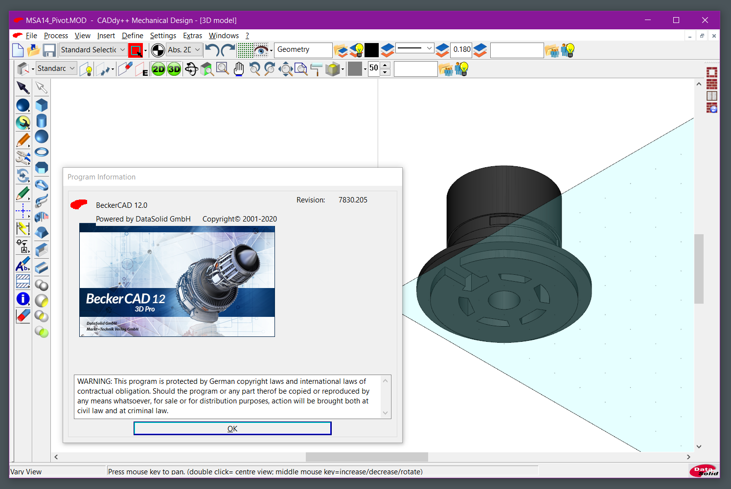
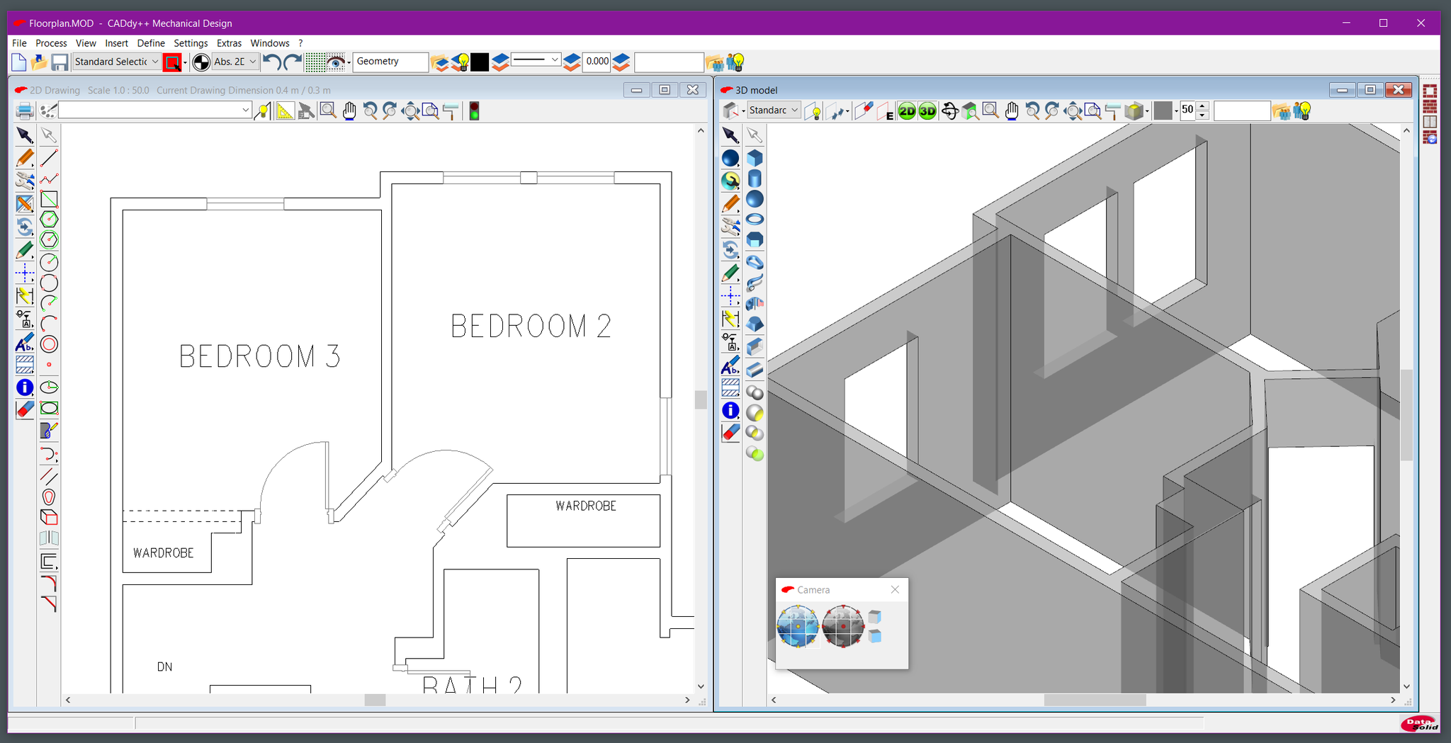
CADdy++ English version showing German labels
I have confirmed that BeckerCAD 3D 12 Pro is a rebranded DataSolid CADdy++ Basic 2019. Telltale signs of that were a prominent CADdy++ label in the title bar of the main window, a DataSolid logo at the bottom of the window and a reference on the splash screen. I've also installed the CADdy++ Basic 2021 and the only difference I found was the product names and minor menu updates. Unfortunately, 3 years later, CADdy++ still has incomplete English translation of their UI and documentation, is not HiDPI-aware, and changes various files within its installation directory, which I've complained about already.
I kept wondering why somebody would use CADdy++, given there are so many better alternatives with a larger feature set. And the answer is that hobbyists are not really a market for CADdy++, and companies which have for some reason selected CADdy++ are in some sort of vendor lock-in and likely use economy/professional editions of the software.
The CADdy++ lineup is as follows (see DataSolid Price list - https://english.datasolid.com/images/stories/DataSolid/CAD/PDF/E-PlMA.pdf)
-
CADdy++ Mechanical Design Professional, €5,990 (~$6800 at the time of writing)
Supports 2D and 3D parametric modeling, and everything in the Economy version.
-
CADdy++ Economy, €3,190 (~$3700)
Supports 2D parametric modeling, ODMA interface, defining 3D models using outlines.
-
CADdy++ Basic, €790 (~$900)
2D drawing, basic 3D modeling.
Then we have Becker CAD editions (prices from Markt+Technik Verlag website):
-
BeckerCAD 3D Pro, €124.99 (~$142)
Same features as CADdy++ Basic.
-
BeckerCAD 3D €79.99 (~$90)
Stripped-down 3D operations.
-
BeckerCAD 2D €39.99 (~$45.49)
Only 2D operations.

Markt und Technik Verlag store listing
Now, if you are a company and in need of a CAD, and you went with DataSolid, you'll likely will go to CADdy++ Mechanical Design Professional/Economy and add a bunch of extra modules (such as sheet metal bending or STEP import/export) to support your design and manufacturing processes. You are unlikely to migrate to another solution since the file format used for the drawings and 3D models is proprietary, and, while you can export 2D DWG/DXF and 3D ASIC solid data, the hassle related to migrating somewhere else may not be worth it.
However, if you are an individual, you will not likely want to spend ~$900 for the basic version.
I know nothing anything about the agreements between MuT and DataSolid, but I suspect MuT wanted a general-purpose CAD in their portfolio, and they went with a rebranded and discounted CADdy++ basic.
BeckerCAD is marketed as being "fully compatible with AutoCAD", which may lure in somebody who expects AutoCAD for $150, and ends up confused. The lack of tutorials and accessible information, and with English version, poor translation quality make the learning curve even steeper.
The Good
A thing that makes CADdy++ stand out is it does not try to copy AutoCAD.
It has a standalone 2D drawing mode which allows focusing on refining the 2D drawings in a familiar paper space with predictable dimension scaling. I know this is a lousy argument, but dedicated 2D and 3D spaces make more sense to me.
They do not clutter the interface with all the operations you can do. This is both good, since it does not present you with 3D boolean operations while drawing a 2D rectangle, and bad, leading one to believe something is not supported because it is not prominently displayed in the ribbon.
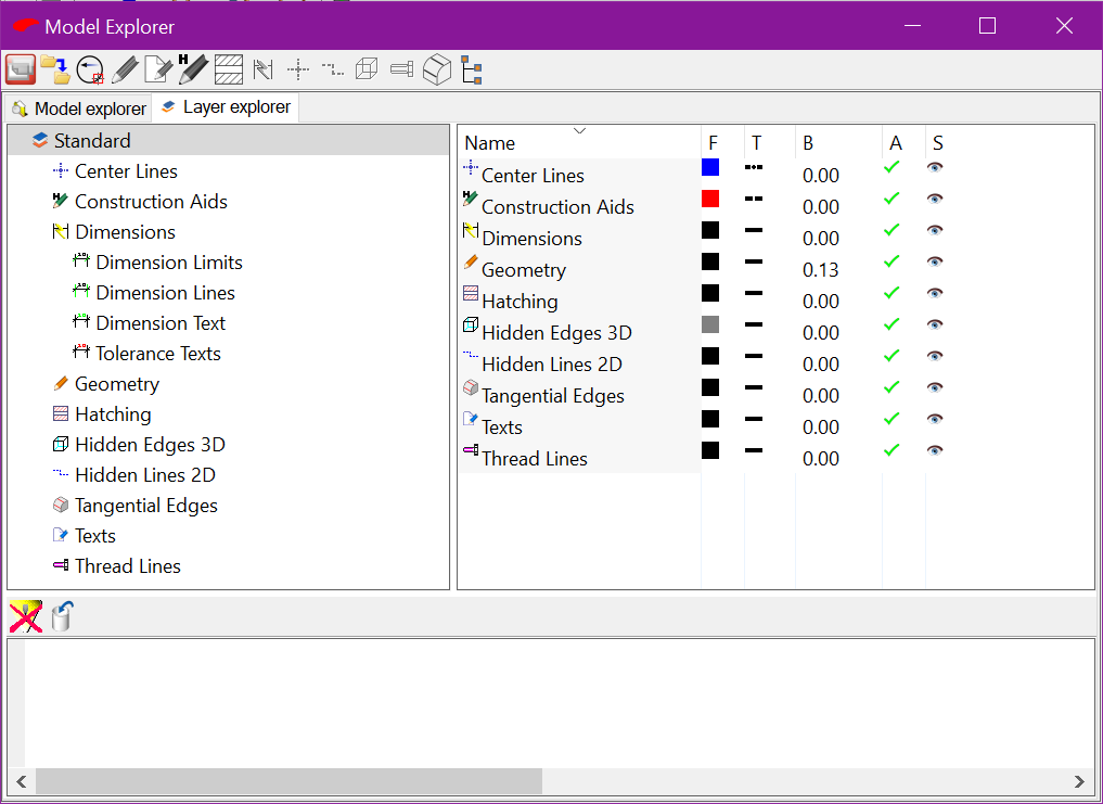
Model Explorer / Layer Explorer
I liked the default separation of drawing elements by layers. Even if your current layer is Geometry, adding a construction line would send that line to another layer. Same with dimensions and other types which can be assigned through the Layer Explorer tab in Model Explorer panel.
There is no separate command line and while there is a concept of commands (and nested commands too), you call them via a button in the interface. However, you still need to enter parameters somehow, and here's where things start to go awkward.
The Bad
This "Status" Window
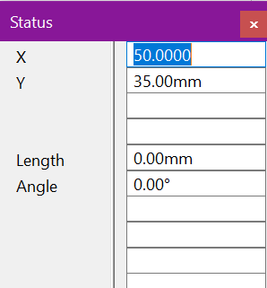
Your operations are decoupled from the parameters, which are entered primarily through Status window (unless you are grid-snapping all the time). The Status window does not work that well on a high-resolution monitor. The action that's being taken is physically removed from the Status window where inputs and outputs are displayed. This has tripped me multiple times, creating unexpected geometry because I did not notice that some value was incorrect.
My snap hotkeys ("e", "l", "s", etc.) constantly ended up in the fields of the Status window because I forgot to press the spacebar.
One can move the window closer to the center of the screen, but then it impedes all operations since the drawing window does not receive cursor events when the pointer is passing above the Status window. Other CAD applications moved this functionality to a docked bar or attach the input fields to the cursor location. You can dock the Status window as well, but its fields can only stack vertically, and the window can't share the docked area, so docking wastes a lot of space.
Font handling
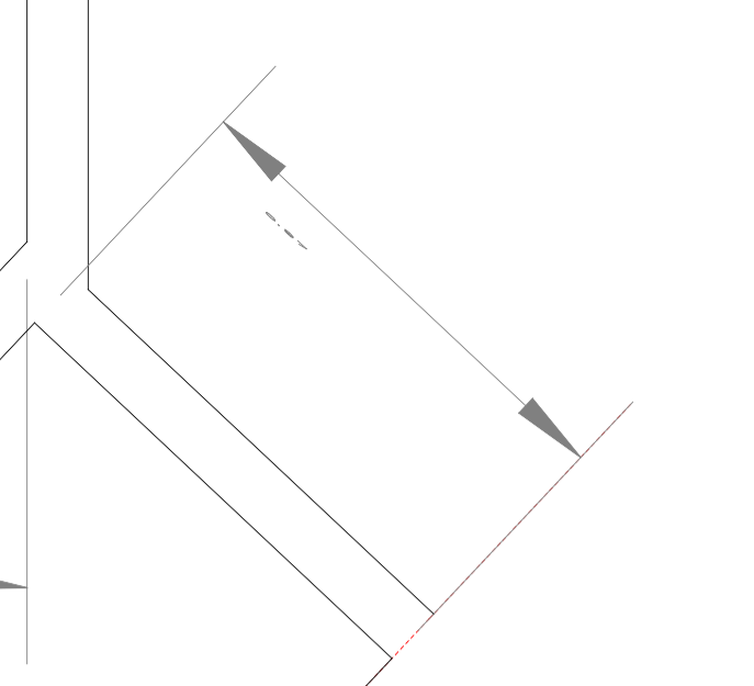
Angled dimension text from BeckerCAD as displayed by Autodesk Viewer
Text handling is generally confusing, starting from the broken TrueType fonts in 3D view to arbitrary sizing of the glyphs resulting in stretched appearance even in default title blocks (aka Standard Sheets). You just need to know your font's dimensions somehow.
Font families are not properly supported, so the application will happily select the Arial Narrow family if you choose "Arial".
2D Drawing Performance
You will notice flickering for all objects in 2D view immediately when you pan/zoom. However, once you reach about 50 objects, you will start noticing redraw sequences. At 500+ visible lines, horizontal panning with a mouse wheel becomes annoying. To me it looks more like a DOS application without hardware acceleration. Copying such drawings into the 3D space removes the lag, so that may be a workaround. You will need to transfer the drawing back to the 2D space to export as .dwg though.
Interoperability
Every 2D drawing I exported from BeckerCAD looked different in the DWG export. Fonts are a particular pain point, with stretched, squeezed or misaligned text elements being the most prominent difference. Dimensions may also look wrong. If you specify the "fit" style, the resulting dimension text will overlap with the dimension line.
The import process for DWG files only reads data from the model space. If the file to be imported has any paper space layouts defined, it will ignore them. While you can import DWG files with 3D geometry, with varying usability after import, you cannot export DWG files with embedded 3D objects.
When exporting drawings to SVG your text elements will have default browser font regardless of what you had in the drawing.
If your workflow only revolves around CADdy++ tools (which is unlikely), you might not notice these issues, however do not expect your drawings to be rendered in the same way in other applications when you export DWG/DXF or SVG. Application listings claim BeckerCAD is "Fully compatible with AutoCAD", however, what "compatible" means is left as an exercise for the user.
Localization
Even though the software is being sold in the US, and there is built-in support for inches, you don't have a way of presenting values as feet and inches, e.g. 7' 2", which are used in US architecture drawings. It would be great for the US to switch to a metric system someday, but for now applications have to adapt to be usable in the target market.
There are no default ANSI paper sizes in the standard.tpl file, so here's my standard-imperial.tpl file containing ANSI and Arch paper sizes.
General Attention to Details
While working with this software, I kept finding items that can be classified as "paper cuts". They are small/trivial to fix issues, which make me question the willingness of the product owner to ship a quality product.
BeckerCAD ships with default hotkeys configuration, which uses commands that are not available, e.g. ".sys.wnd.openToolWinMenu".
Symbols shipped with the program have "interpret size related to paper size" option set, which causes the contained text to be HUGE, and the only solution is to disassemble the symbol and update this text attribute.
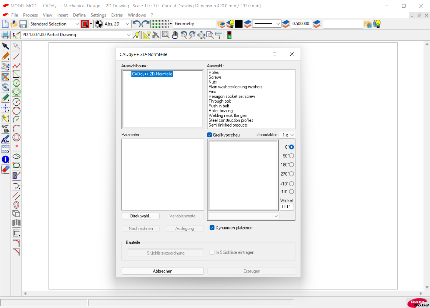
I mentioned the translation issues before, and Symbols shipped with BeckerCAD are all in German regardless of your installation language.
Single-clicking the symbol in the palette does nothing, double-clicking it would insert it at a random location in the drawing as well as allow to place a copy where you want it, so you must use the "OK" button.
The annoying modal dialog boxes you get when you execute a command outside of the proper context (e.g. Enabling snapping when there are no drawing commands) can be redirected to a Model Explorer tab message box. However, that text area does not wrap words, resulting in truncated visible messages. You'll need to scroll horizontally to get to see the full message.
You can't create a line with a parallel line tool to have an overlapping "straight line", since the application will exclaim "Only positive entries permitted!". The application generally likes to shout.
Future Concerns
The way the application stores its configuration files and databases makes it incompatible with Microsoft Store or deployment via .appx installs, so the product relies on customized installation path. While this is not an immediate concern, seeing the same behavior in the 2021 does not bring joy.
The .MOD files created by application are proprietary and DataSolid sells standalone viewer software to view and print the drawings and models outside of the editor. CADdy++ View & Plot will cost you €640 (~$730) and a Pro version of that will be €900 (~$1024). Seeing how other players distribute free viewers, I can't help but wonder who the target audience of that is and what it means for archives of your models in CADdy++ format.
The application ships with Python runtime v2.7.8 released in 2014. Note that Python 2 support officially ended on Jan 1, 2020.
Likely Audience
I've tested BeckerCAD drawing a real-world floor plan, designing and re-designing a small 3D-printable part covered in the next section, and browsing a bunch of DWG files - samples and real-world drawings.
Even though there are architectural symbols included, I don't think you will want to draw floor plans with BeckerCAD 12. The application does not treat architectural symbols in any way different to plain lines, so you are in charge of the alignment and scaling. Simple floor plans may work. You can use the built-in "Building" functionality, which allows creating a 3D model out of your floor plan. However, it is limited to a single floor and there are no standard 3D models for any of the architectural objects, so your 2D door symbol does not magically become a door in 3D.
That's why I believe this software is better suited for modeling standalone objects.
Designing in BeckerCAD
Now, in order to test BeckerCAD with a useful real-world task, I attempted to fix an annoyance of a Dell MSA-14 monitor arm, which was always slightly tilted because of an undersized pivot shaft. After a few days of measurements and modeling, I made the following subtle change:
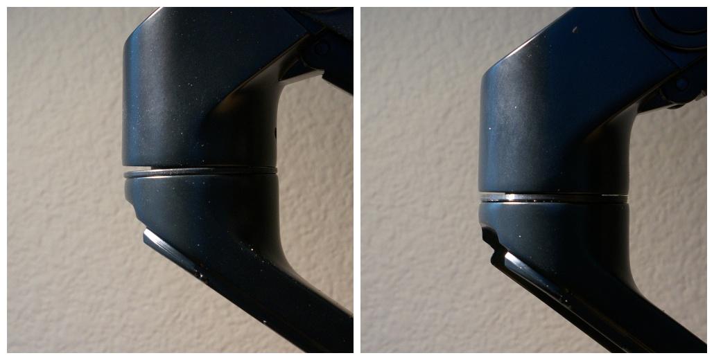
Before (original) and after (3D-printed part)
I probably got a 20% decrease in tilt after printing the part slightly bigger than the original, and while it probably was not worth doing, I learned quite a bit.
I have gone through 10 iterations of this part in the past month, so I am pretty sure my measurements are as good as I could get them. Since I don't own a 3D printer and my experience with such devices has been troublesome, I sent the STL model exported from BeckerCAD to a local shop, jinxbot.com. It was quite a feeling of accomplishment to receive a printed version of something you've spent so much time looking at in the virtual space.
The printed part had perfect dimensions, but it turned out that my cheap calipers had a constant -0.2mm offset while measuring internal diameters because of a manufacturing defect, and it took some force to get the bolt and the nut to seat properly. Subsequent revisions had this issue rectified to the best of my ability.
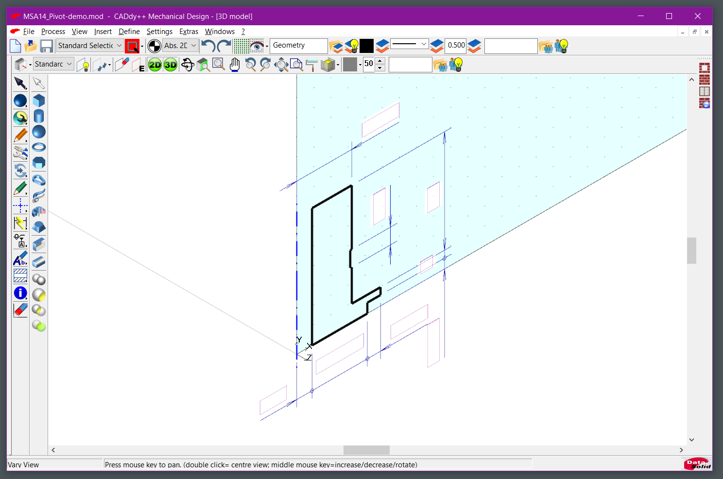
I start with the 2D space and draw an outline of the profile for half of the part:
Then copy this profile into the 3D space, selecting the ZX workplane.
Default dimensions using a TrueType font got replaced with box outlines.
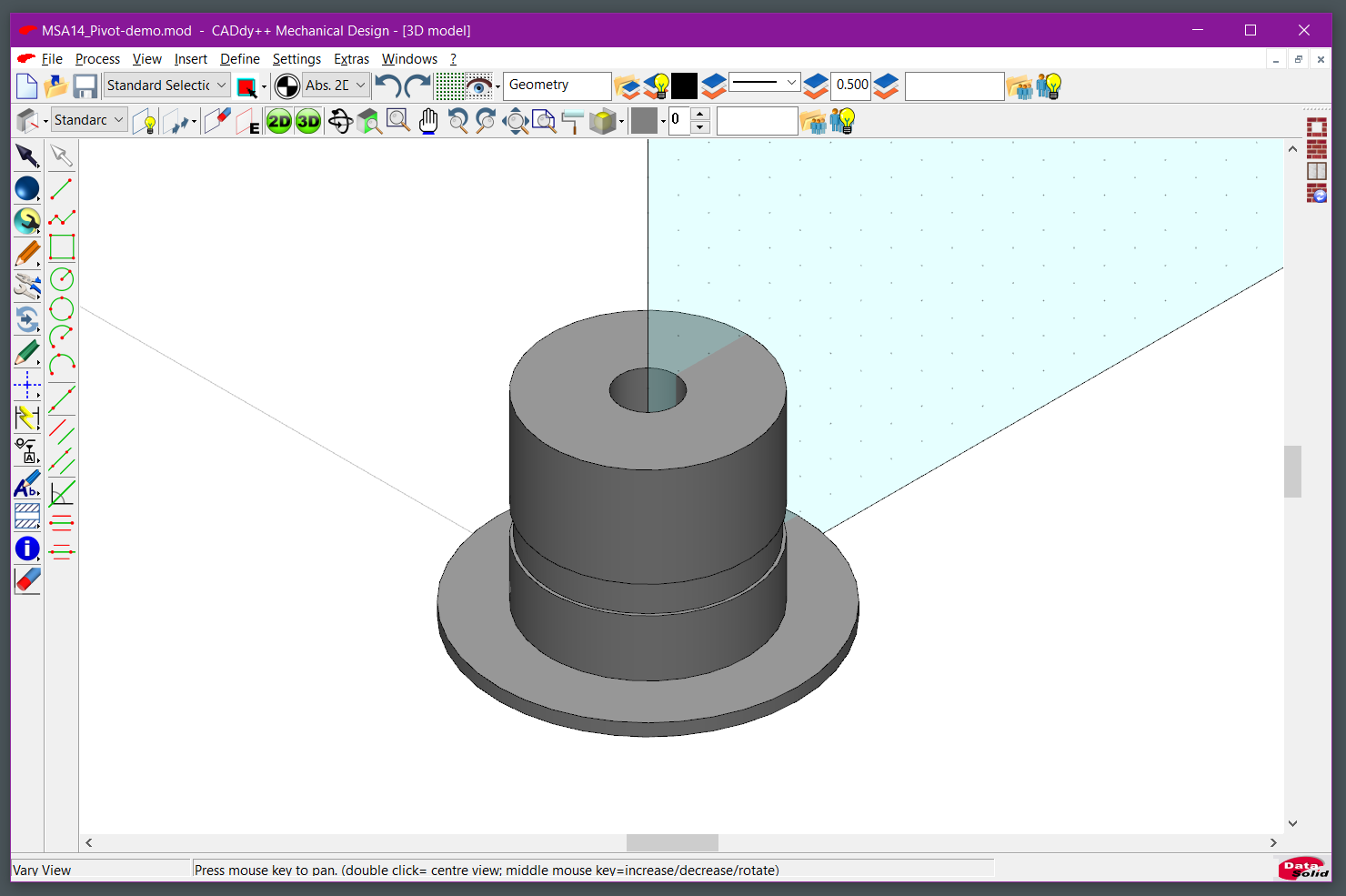
I create a rotational solid using the centerline as the rotational axis. After selecting Process/Erase active 2D section I have a cleaned up 3D view:
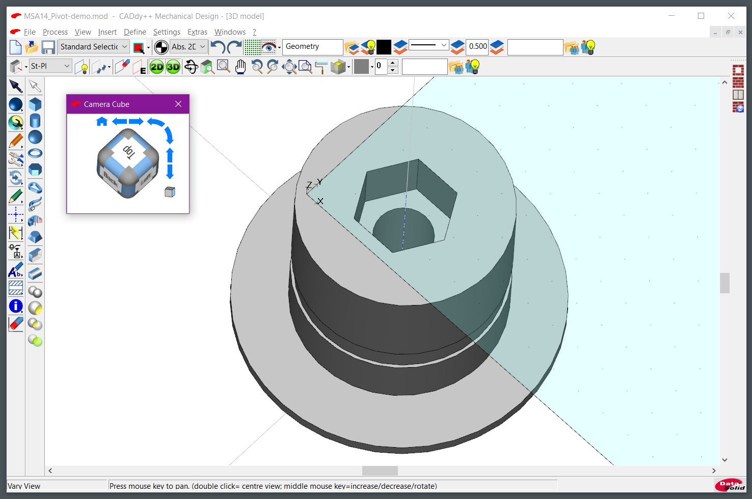
Since I need a place to insert the nut on top, I am adding a "prism" on top by creating a temporary workplane, creating a 15.6mm diameter prism with 6 faces, extruding it down 10mm, and then subtracting it from the model:
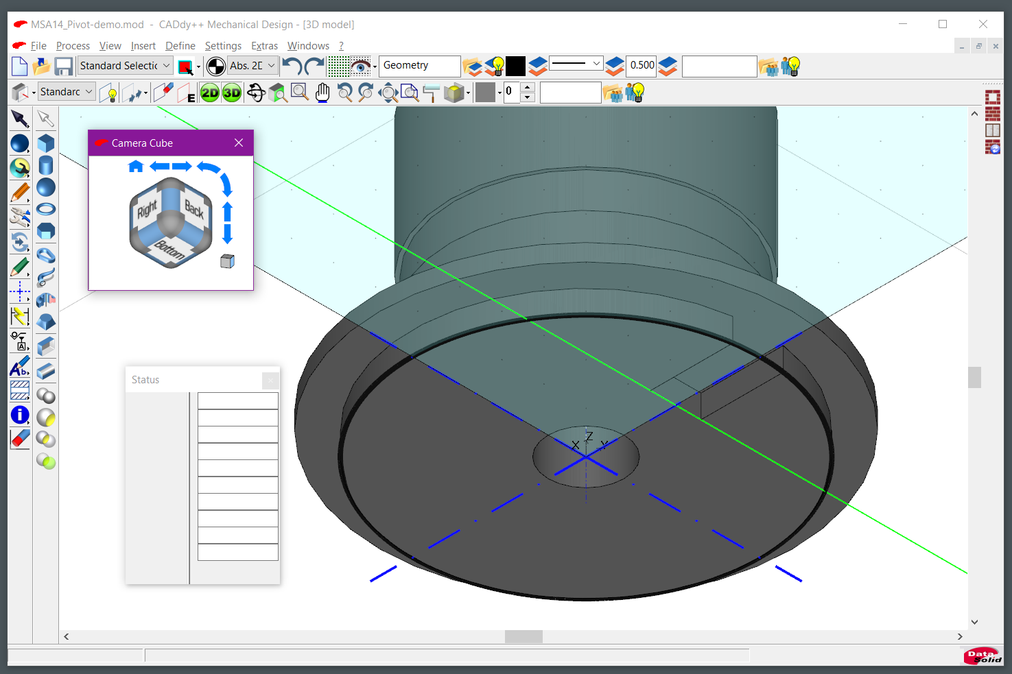
I need a notch on the bottom to prevent the part from rotating when installed. So I create a solid rectangle and run a boolean subtraction operation on the model. This is tricky because I found no way to snap to 3D objects other than endpoints intersecting with the workplane, so using 2D tools I project the base cylinder to the Standard XZ workplane, create a centerline, measuring 10mm from the outside diameter and a 3D box with 10mm depth, 2.75mm height and 6mm width. I carve the hole by boolean "Subtraction" from the main model:
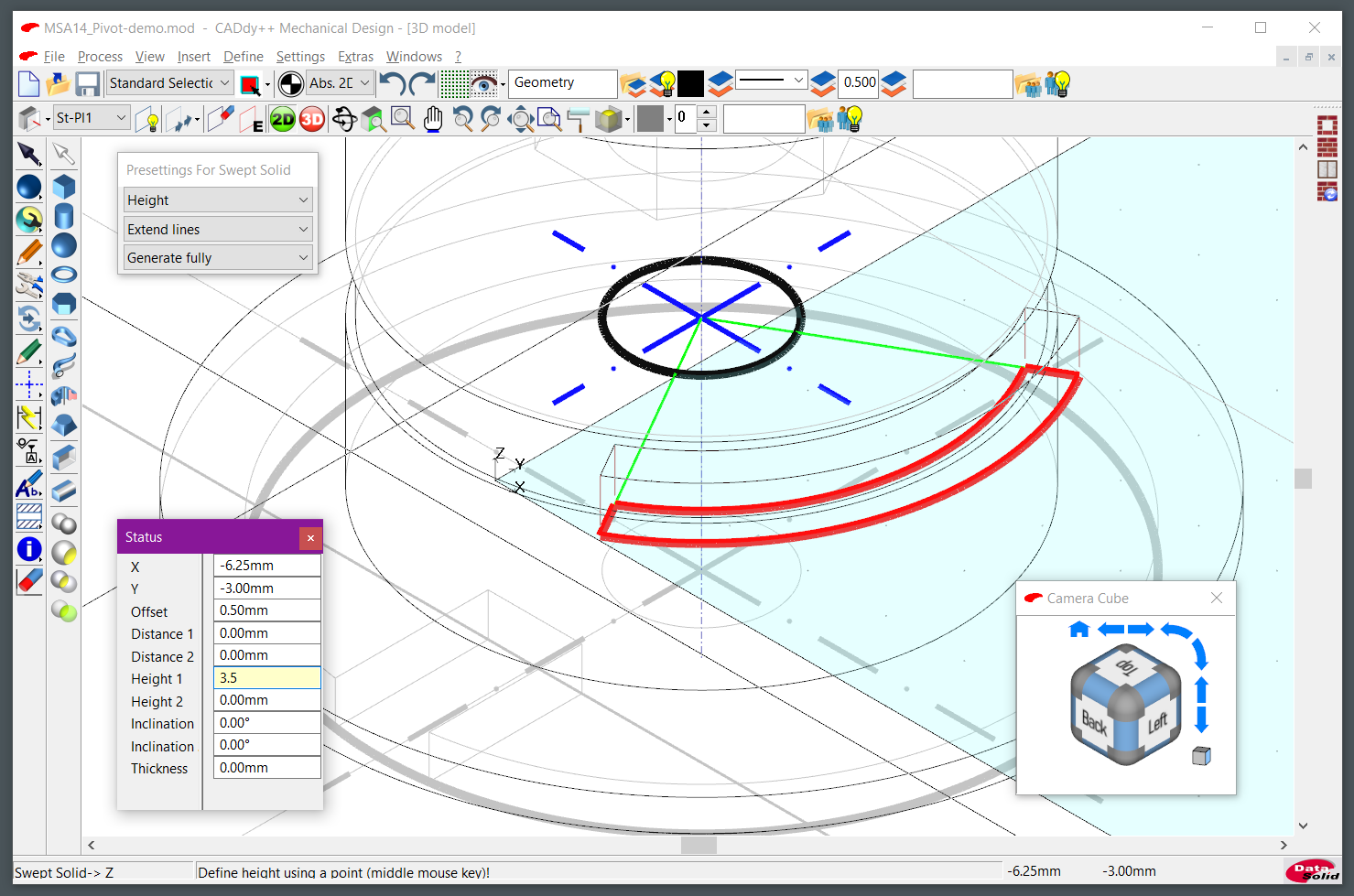
The pivot shaft has a groove that restricts the rotation angle to 90 degrees. I don't know of a better way to do that than to create a tool with an arc, extrude it and then subtract from the model. Based on my measurements, it is offset from the centerline by 30 degrees and is 90 degrees long with 15.15mm radius.
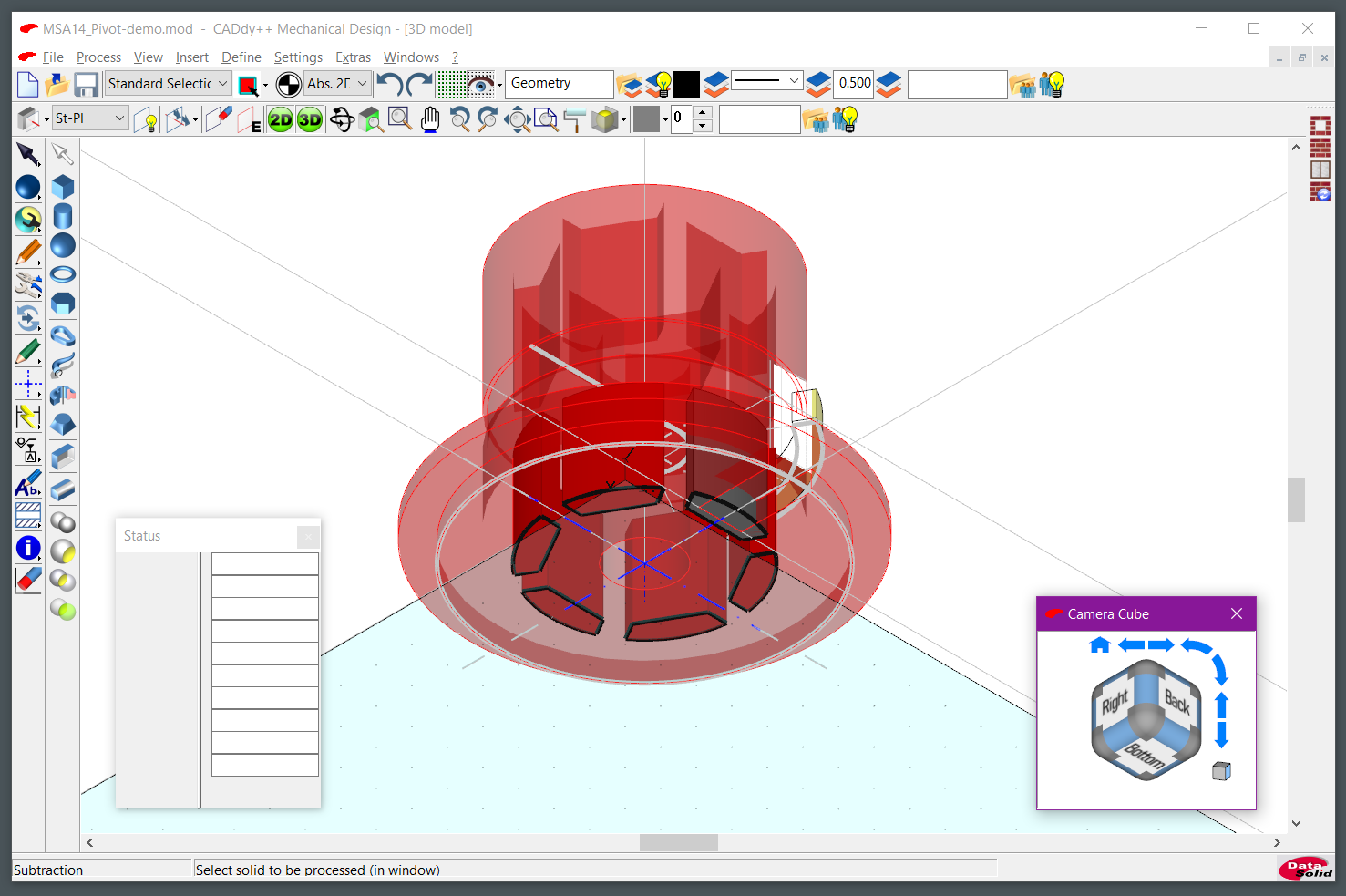
That's it, basic shape is done. Now, since I wanted to be fancy, I also removed some material by creating edges instead of solid infill. For that I re-used the top face workplane do draw a circle 3mm smaller than the outer diameter and a hexagon 3mm larger than the nut opening using Parallel Line/Contour 2D tool. Joined them with another 3mm bridge, cleaned up all of the extra lines, then created an array of these "holes". Then I extruded them downwards 15mm, merged into a separate solid, moved the workplane to the origin and extruded them up 12.75 mm:
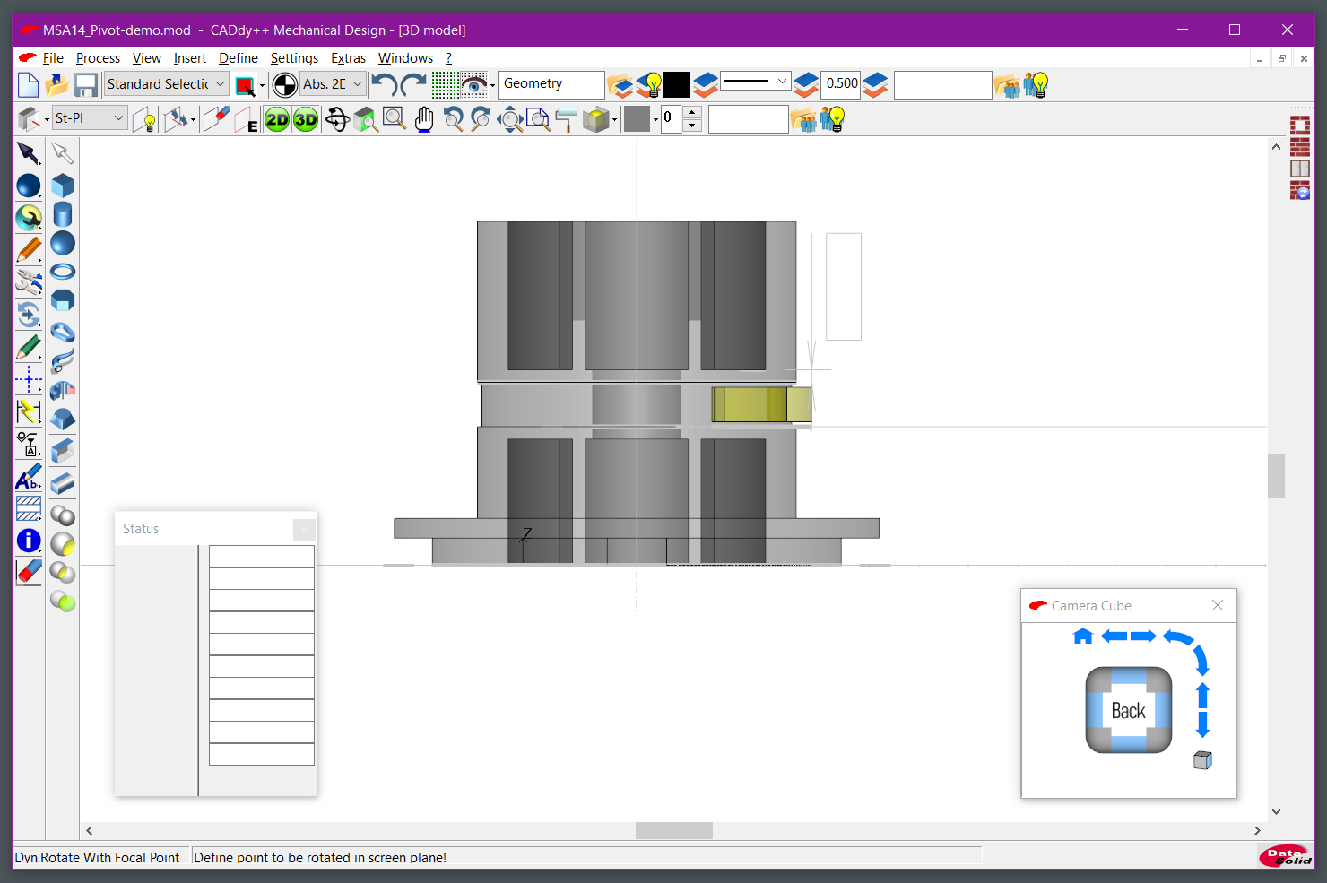
I left the created arc "tool" in the final drawing, it's a transparent yellow chunk.
Then I "subtract" these "holes" from the main model:
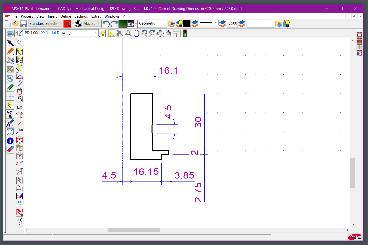
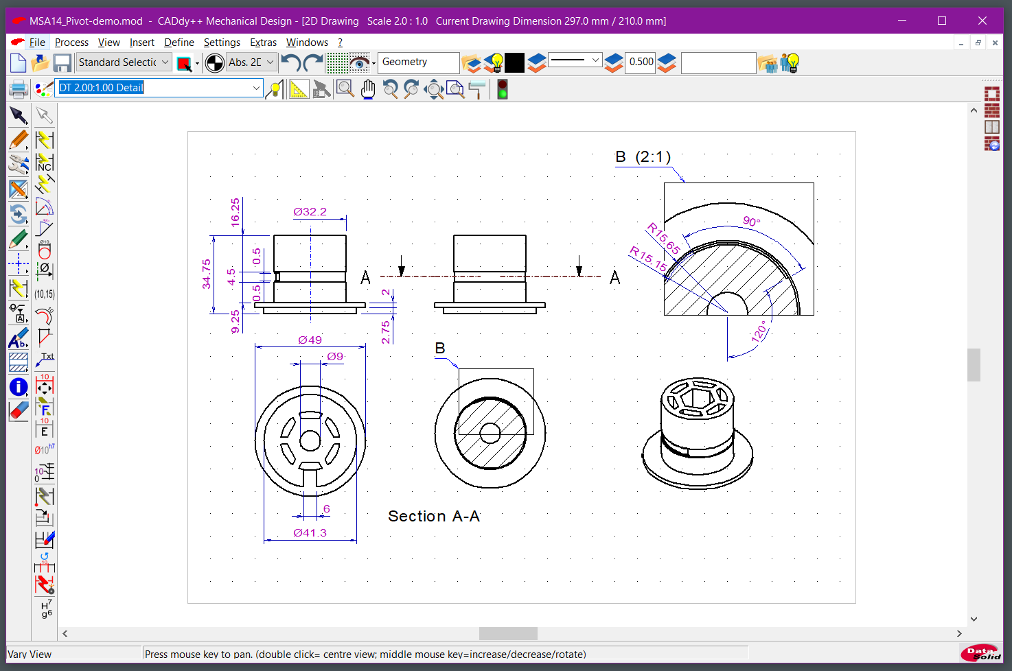
Now I am done with the actual model. now I can create model views and add dimensions and sections for reference.
I am 99% sure this style of dimensioning and drawing would score F- in some design school, but all I wanted from this process was a printable STL file, so everything else is extra:
The resulting model can now be displayed online, using the exporter producing a web page, which apparently, comes from another DataSolid product, CADdy++ Event Planning.
You may wonder why the default camera view is inside the model. Click the "Home" button to switch to the starting position, because for some reason the viewer does not start in starting position.
Downloads:
msa14_pivot-demo.mod - CADdy++ Drawing
msa14_pivot-demo.stl - STL export
msa14_pivot-demo.dwg - DWG export for the 2D part
msa14_pivot-demo.sat - ACIS SAT export of the model
Lessons Learned
Common
2D vs 3D
You can start in either 2D or 3D. If you don't need 3D, you can close the 3D view and forget about it. If you expect to transform your 2D image into 3D, then you have two choices:
Start in 2D, draw the edges, outlines, and everything else you can for a single projection, then use "Transform/Move with Copy Dynamically" to copy the drawing into the 3D space plane.
Start in 3D on one of the Standard XY, XZ, and YZ plane. Use 2D primitives in the same way you'd use in the 2D view, and/or 3D shapes.
Hotkeys
By default BeckerCAD ships with Hotkeys.txt file in Program\Bin directory which has the default settings. Copy that file as user_hotkeys.txt file to your working directory (by default that's C:\BeckerCAD12\User, but, as mentioned in my first post on BeckerCAD, it can be anywhere you want) and edit it.
You can find the names of the commands to use through the View/Toolbar dialog. You don't need to create a new toolbar.
If you select the nodes of the tree on the right, you'll get information in the Function area, e.g. "Top View" is mapped to command .view.dirTop. Some of the entries in the default Hotkeys.txt don't work, since likely they changed the functionality without updating the file.
Fonts
BeckerCAD 12 3D Pro ships with 14 vector fonts in a proprietary format in Program\FNT directory.
TrueType fonts can be used, however they are not visible in 3D space unless you enable outline property of each individual text object.
2D
Partial Drawings
A 2D drawing is built from Partial Drawings, which contain objects such as lines or circles, or groups of such objects. By default, you get a Partial Drawing (PD) and a Standard Sheet (SSH). Standard Sheet is used for placing a title block and Partial Drawings are used to create a composite of your drawing. Your geometry goes into a Partial Drawing, and detail views are created in separate Detail View Partial Drawings (DT).
3D
Workplanes
Workplanes are used to create a reference point for subsequent operations. By default there are three Standard workplanes. I create new ones to draw 2D lines on top of 3D faces by first "Define WP using Face/Center of Gravity", and then drawing what I needed in the new workplane.
We can convert Workplanes to "Cut Planes", which allows exposing an internal structure of the model as if it was cut. This, however, has no relation to section view, which you can create in 2D mode from a model view.
Push/Pull
BeckerCAD 3D has an Offset Faces tool which functions similarly to Push/Pull tools in other applications and can be found in "Solid Local Operations/Offset Faces" 3D toolbar. You will see the changes in the 3D view or specify the offset in the Status window, which then can apply to other faces.
Troubleshooting
-
I can't get the camera inside the model
By default, you are in an orthogonal projection, which will always show a face perpendicular to your view. Switch to the Perspective mode on in View -> Perspective/Orthogonal and then you'll be able to zoom into your model.
-
Measurements appear as boxes in 3D view
If you are using a TrueType font for dimensions or text, it will be displayed as boxes in 3D space because of limitations of BeckerCAD. Select a vector font in Settings/Text.../Text Style/current font for specific styles.
-
I can't select anything
If you receive "No valid object found!" or "Point no found" when clicking on an entity you expect to select, check the following items:
-
You have the correct Partial Drawing selected in the 2D menu bar.
Active Partial Drawing selector is set to either the "Select on current sketchboard only", "Select on all sketchboards", or, if you need to use "Select on listed sketchboards", click the "Define Activ (sic) Partial Drawings..." icon and select the Partial Drawings you need to interact.
Partial Drawing appears to be the same thing as sketchboards in BeckerCAD 3D localization.
If you regularly switch between the Partial Drawings, enable "Show/Hide status of partial drawing" (enabled is grayed-out) to gray-out ("lowlight") the geometry on a Partial Drawing that's not currently active.
-
The object you are trying to select belongs to a layer that's "pickable", or "active".
Open the Model Explorer, click on the Layer Explorer tab and open Properties... menu for the layer your object is located (e.g. Hidden Lines). If the "Active" state is off, then you won't be able to select it, or use the "Activate Layer" icon to switch the layer to that element.
If you are in 3D view, then check the following items:
-
Your 2D/3D selection buttons are what you expect, if the mode is not selectable, you cannot select geometry of that kind:
Green background/black text = selectable.
Red background/white text = not selectable.
-
Your camera view does not match the current workplane, so your dimensions are projected to the wrong workplane.
Switch to a workplane which has the projection of your geometry that you want to measure/or reference for other commands.
-
-
Low STL Export Resolution
SAT and STL export settings live in "General 3D Import / Export Settings" dialog that's only accessible from File/Export/Settings. If your STL files appear to have low resolution, check the "Settings stereo lithography" group in that dialog. In my case, setting normal deviation to 5 has increased the polygon count for the arcs in the export.
-
Status Window Does Not Show Up
Status window can go out of display bounds. In this case, select View/Status Dialog Box, then without moving the mouse, press Alt+Spacebar to get the Windows menu allowing to move the window. Select "Maximize", which will bring the window in and maximize it. Then use your mouse to resize the window and position it within the viewport. If your status window cannot be properly positioned, that may be due to Windows scaling. Disable scaling for the application in the shortcut settings.
Afterword
It was an interesting experience, and I learned a lot. I hope DataSolid fixes the paper cuts, and that CADdy++ and BeckerCAD improve enough to be featured more on the internet, but for now I have exhausted my patience and will happily search for another thing to learn the hard way.